Uplift Rebuild Part 8 – front armour, power light and safety link
21st July 2024
At the moment Uplift’s wheels are protected at the sides, but not at the front:
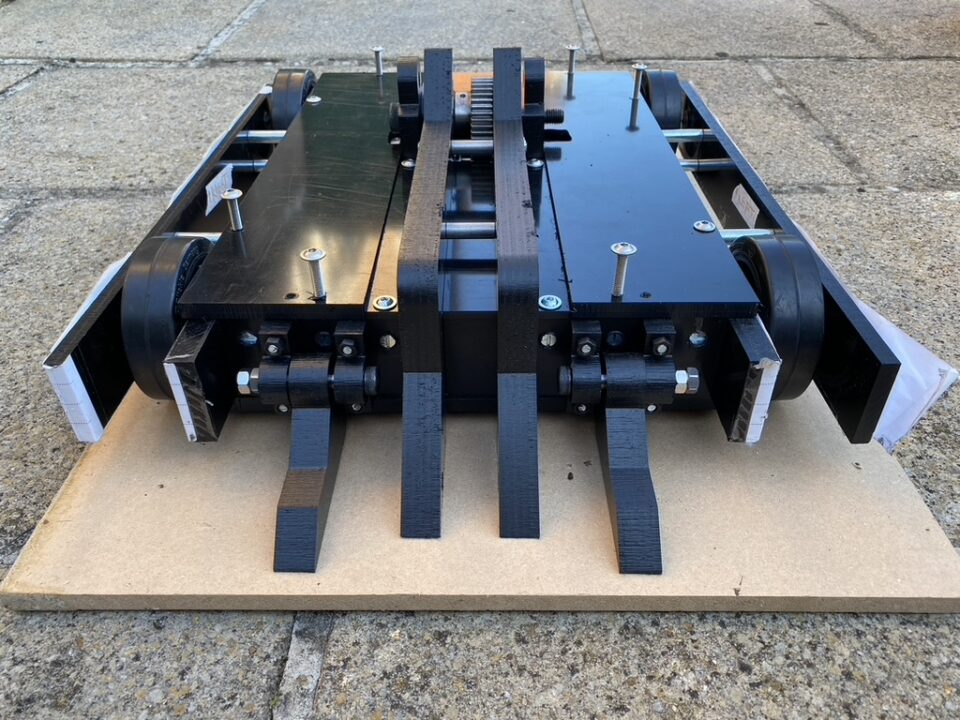
The front edges of the side armour and main frame rails are also exposed here and very likely to pick up damage. The main frame in particular is something I don’t want to have to remake very often and other than this front edge it’s quite well covered.
I made up some small armour pieces from 20mm thick HDPE. For weight saving most of the material has been removed so the effective thickness is only around 5mm in some places, however they overlap neatly over the front edges of the frame and side armour giving some protection:
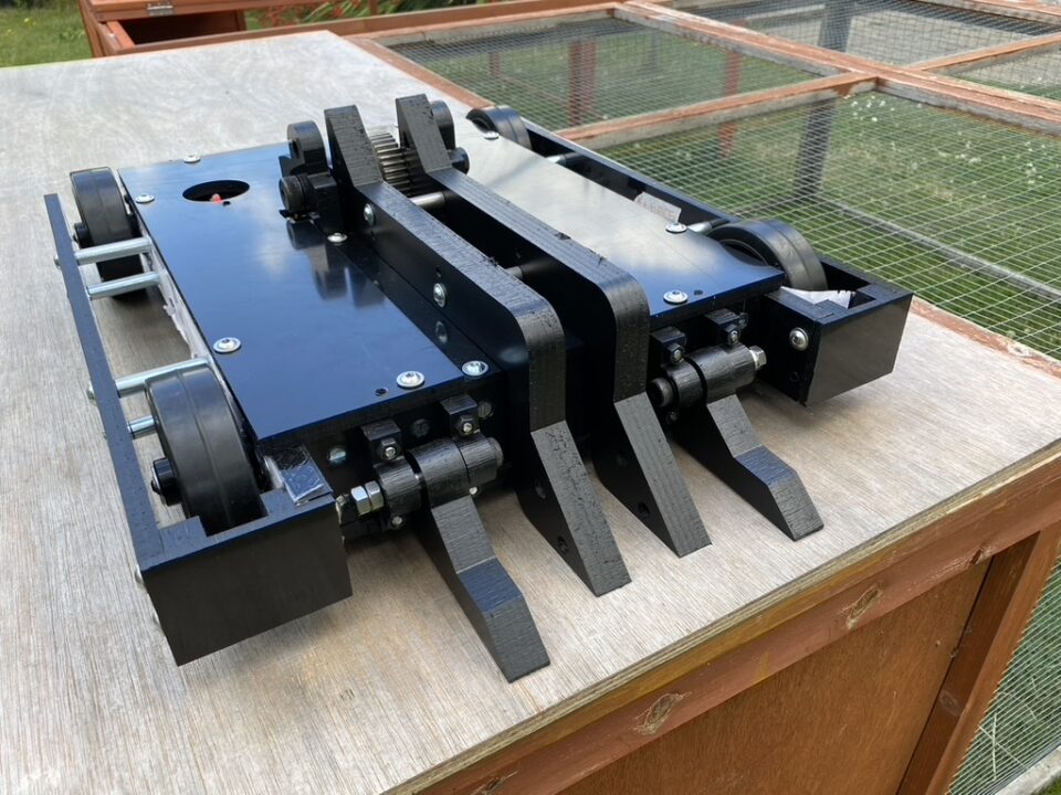
I may want to add some vinyl decals to these panels, so they are mounted from the side using long bolts all the way through the armour and into the main frame, keeping a nice clean look at the front.
I expect these will take quite a bit of damage from impacts with other robots but they are easy to remake and should stop those impacts directly hitting the wheels, frame or side armour (all of which are more difficult and/or expensive to replace).
Power Light Mount
While I was working on the front armour, the 3D printer was producing a mount for the power light. Power lights are a safety requirement to show visually when a robot is switched on.
Uplift uses a 24v LED mounted through a hole in the top panel, however I didn’t want the LED physically mounted to the panel itself because the top is something that gets removed extremely often and having wires permanently attached to it is less than ideal.
I therefore designed a mount that would attach to the base of the robot and put the LED at just the right height to poke through a hole in the top panel:
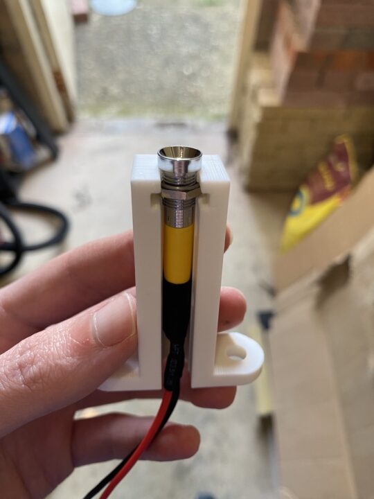
The mount is printed out of PLA using 70% infill to make it pretty solid. Hopefully this will be strong enough for a sportsman robot but I’ve made a couple of spares just in case.
Removable link
While on the subject of safety requirements, I also finished the mount and cover for the removable link. This link essentially is the switch to turn the robot on and off, and is made using an XT90 connector with a loop of wire between the two terminals. This is pushed into a mountable XT90E-F to complete the circuit.
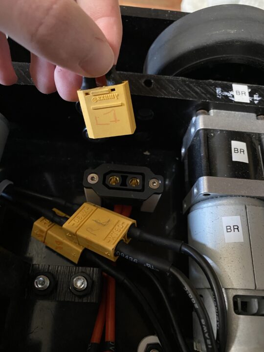
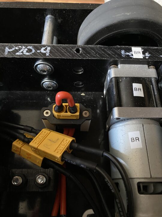
The XT90E-F is mounted using two M3 bolts into the base of the robot, with some 3D printed spacers to hold it at the right height. Like the LED mount these are just PLA but this time non-structural – with the bolts also running all the way through to reinforce them I’m not expecting any major issues here.
The link needs to be accessible without using any tools from the outside, so I cut a 50mm hole in the top lid above where the link was mounted and made a slideable cover to protect it during fights:
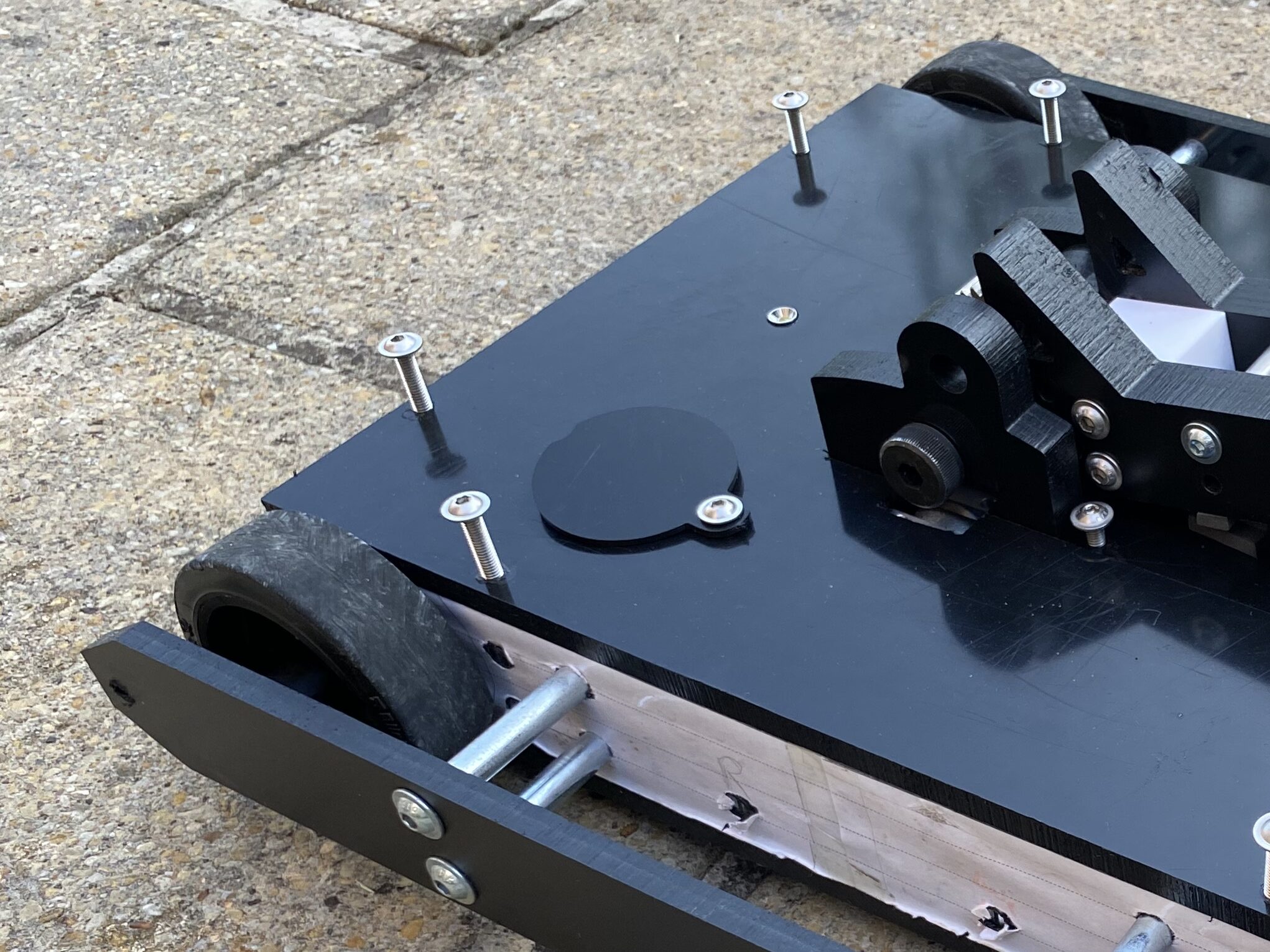
There’s a small lip on the inside to hold it in place, so this should be easy enough for a person to open when needed but otherwise stay secure.
