Uplift Rebuild Part 4 – Adding a lifting arm (Pt 1)
31st March 2024
Back in 2017, before Uplift became Uplift, the plan was to add an electric axe powered by a scooter motor. This approach is used by many robots, however I realised once I had built the main frame and added the drive motors that weight and space for such a weapon was looking more than a little tight.
Conveniently, over the last seven or so years that Uplift has been sitting dormant in the garage, I have accumulated almost all the parts needed to make a lifting arm powered by a high reduction gearbox and cordless drill motor.
This will just about fit inside the frame and because the motor is so much smaller, even the motor + gearbox + final stage spur gears needed to make the lifter capable of hoisting 13+ kilograms is lighter than the scooter motor that was originally planned.
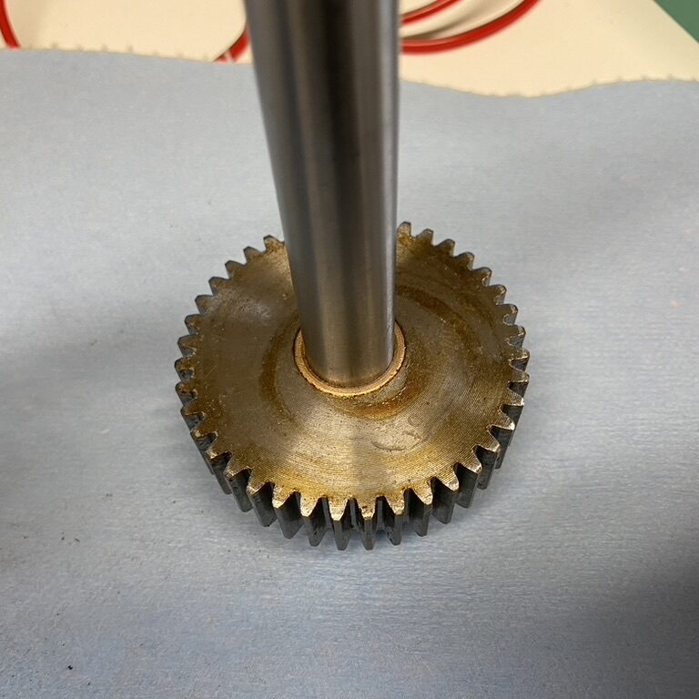
A lifter it is then! I had an Oilite bushing that would press fit into the bore of main spur gear, however as I own no press I had to make do with a block of wood and a rubber mallet. Slightly scary, but the end result was perfect:
The next job was to make some supports that would sit centrally in the robot and hold the axle that the lifting arm would pivot on in place. Using an online spur gear centre distance calculator I worked out what height the axle would need to be above the gearbox for the 14 tooth gear on the gearbox shaft and the 40 tooth gear on the axle to mesh properly and went from there.
These first supports have come out a bit weedy, but they do the job for now. I kept their chunkiness as minimal as possible to bring the weight down, as I figured I could add some more material back in later versions once the robot was more complete and I knew how much weight I could spare. For now, just having something that held the the lifter in the right place was all I needed.
Here’s the supports in the main frame – I was still working out exactly how far forward or back I want them:
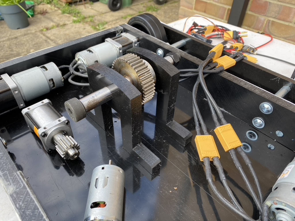
The lifter axle is a 16mm diameter steel shoulder bolt, which should be plenty strong enough. The only one I have at the moment is a little long so I’ll probably get a shorter one at some point.
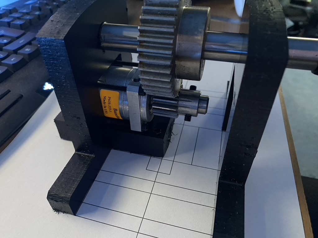
I made up a mounting block for the 132:1 Banebots P60 gearbox to sit on. This will just bolt directly into the baseplate, independently of the lifter supports. Upon checking the meshing of the gears it looked like I’d got my earlier centre distance calculations correct!
Having decided roughly where in the robot I wanted the lifter to be mounted, I drew and printed off a template with markings for where all the mounting holes needed to be drilled in the baseplate:
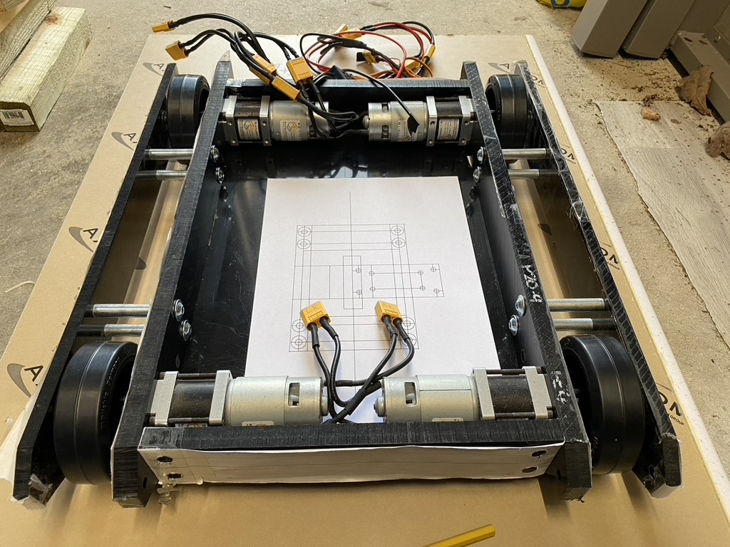
Drilling all these was another scary operation – I really didn’t want to mess up and have to make another baseplate. Fortunately, all went OK. This was the first time I’d used my new centre punch for marking holes in material – it’s a very simple tool but made this whole process so much easier and more accurate.
Once I’d drilled a few of the holes I bolted the lifter mounts and gearbox in place to check the alignment was all OK – fortunately it was!
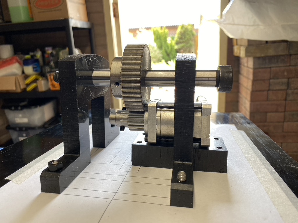
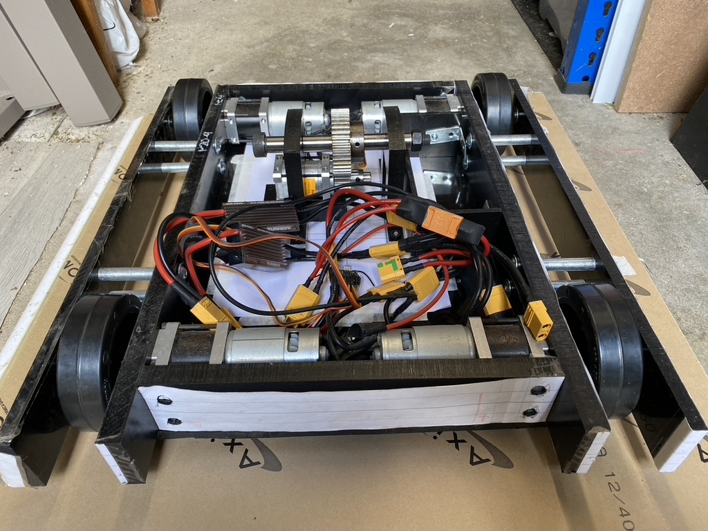
Here’s the full assembly now mounted in the robot:
