Uplift Rebuild Part 5 – Adding a lifting arm (Pt 2)
28th April 2024
Now the lifting arm supports are in place, it’s time to start thinking about the lifting arm itself.
The arm will actually comprise of two separate “arm” pieces, connected together by bolts going through some threaded spacers. The spacers will leave a 30mm gap in between the two arms, giving enough room for the 40 tooth spur gear and a bit of wiggle room I can fill with washers if needed, so that the gear can be positioned perfectly above the 14 tooth gear on the lifter gearbox shaft.
The exact positioning of both the final stage lifter gears on their respective axles is still a bit TBC at this point. I’m hoping they’ll end up perfectly centred, but may not depending on how the 14 tooth one best sits on the gearbox shaft.
I wish I could say I had a detailed plan for the arms and carefully worked out all the required dimensions for the optimal lifting setup, but the reality is I made some very rough measurements to make sure whatever I designed reached the front of the robot (clearing the front of the frame) and would rest on the floor, then did a quick sketch in Fusion 360 of something that looked like it might work.
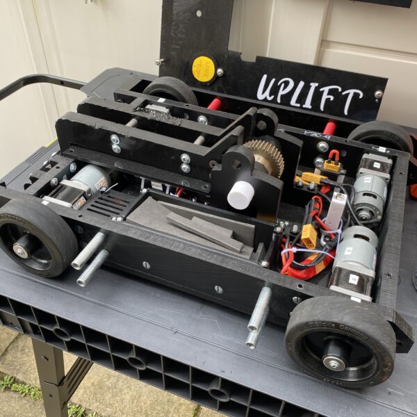
Amazingly this gamble paid off and although the arms aren’t perfect they are definitely useable and fit quite well on the robot:


They are made from 20mm thick HDPE and seem sturdy enough, especially when joined together. I think I’m still going to add some (non-lifting) front forks either side, partly to help getting under opponents but also to protect the lifting arm from big sideways knocks.

